
Integrating Electric Overhead Traveling (EOT) cranes into an industrial shed or manufacturing plant introduces complex dynamic loading conditions that differ drastically from standard static warehouse buildings. When a 10-ton or 20-ton crane lifts, starts, stops, or travels along its runway, it transmits substantial vertical, horizontal lateral, and longitudinal impact forces to the supporting structural frame.
For industrial investors and plant managers in heavy manufacturing hubs, overlooking these dynamic forces during the design phase can lead to structural fatigue, crane rail misalignment, and costly operational downtime. In this technical guide, our senior structural engineers detail the critical parameters required to design a safe, robust EOT crane shed.
1. Dynamic Load Distribution and Impact Factors
Unlike dead loads (self-weight of steel members) or live loads (roof maintenance), crane loads are inherently dynamic and cyclic. According to IS 875 and IS 800 specifications, structural engineers must incorporate specific impact allowances:
- Vertical Impact Allowance: Typically 10% to 25% extra load added to the maximum wheel load to account for sudden hoisting vibration.
- Horizontal Lateral Force: Usually 5% to 10% of the combined weight of the crab and lifted load, acting transversely to the runway rails.
- Longitudinal Surge Force: 5% of the maximum static wheel loads acting parallel to the runway track during crane braking.
Engineering Pro Tip
Using STAAD Pro advanced finite element analysis, our team simulates multi-cycle crane movements to ensure gantry brackets and column corbels absorb cyclic stresses without fatigue cracking.
2. Gantry Girder and Bracket Design
The gantry girder supports the crane rail directly beneath the bridge wheels. Designing this girder requires careful deflection checks:
| Design Parameter | Standard Warehouse Building | EOT Crane Industrial Shed |
|---|---|---|
| Primary Columns | Lightweight I-Sections / ISMB | Heavy Tapered Built-Up Sections with Corbels |
| Gantry Girder Deflection Limit | Span / 325 | Strict Span / 750 or Span / 1000 |
| Roof Clearance Hook Height | Standard eave height | Calculated clearance above maximum lift hook level |
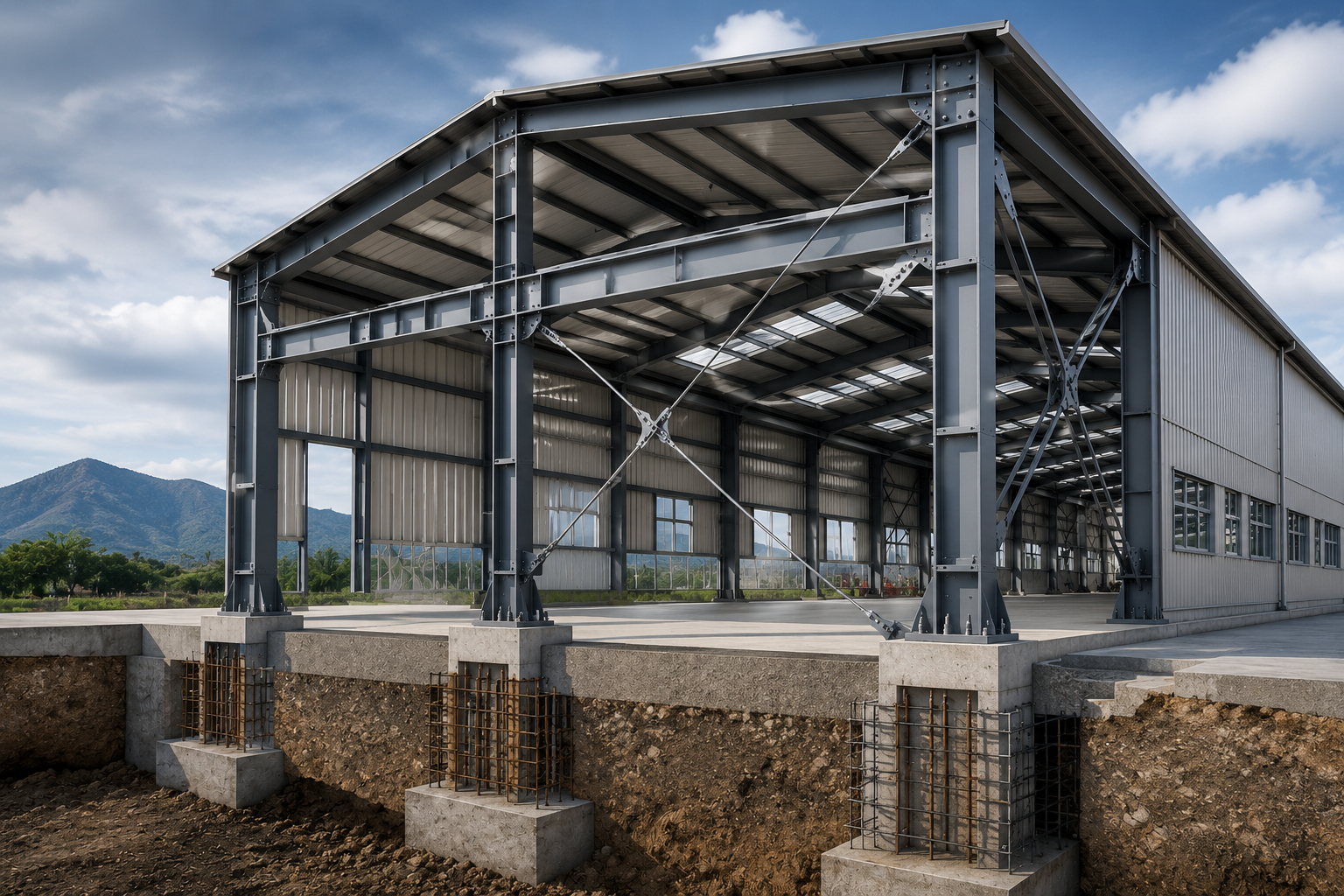
| Foundation Requirements | Standard pedestal pads | Deep reinforced concrete moment-resisting footings |
3. Ensuring Adequate Hook Height and Clearances
One of the most common operational errors in industrial shed design is miscalculating the clear hook height. The clearance from the floor level to the underside of the roof truss must account for the maximum lifting height of the hoist, the sling height, and the height of the tallest machine or component being transported across the shop floor.
Conclusion: Trust Professional Structural Detailers
Designing an industrial shed capable of housing heavy EOT cranes requires rigorous mathematical modeling, precise welding standards, and high-tensile steel members. Partnering with Rajveershree Engineering guarantees your facility complies with all IS safety norms while optimizing overall structural tonnage.